Showing posts with label 8051. Show all posts

Tuesday, February 12, 2008

8051 Development Tools

Assembler

  • ASEM-51, by W.W. Heinz, is a free 8051 macro assembler for MS-DOS, Windows and Linux.
  • Download ASEM-51 v1.3 and unzip it into a sub-directory.
  • Issue "ASEMW DEMO.A51" within DOS box will process the source file "DEMO.A51" and generate a output file "DEMO.HEX" in Intel-HEX format and a list file "DEMO.LST" in plain text.
  • Refer to "ASEM_51.DOC" for detail usage. The example program "DEMO.A51" is very instructive.
  • "ASEMSYM.EXE" is a small utility by Chin-Shiuh Shieh which accept list file from ASEM-51 and produce symbol definition file for NoICE51.

Simulator


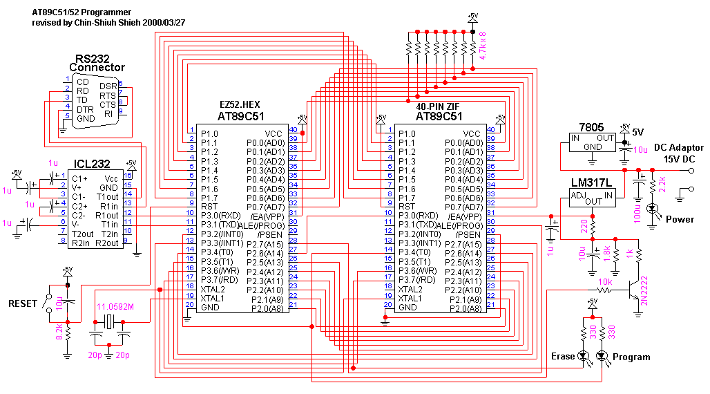
AT89C51 Programmer

AT89S51 Programmer


In-Circuit-Debugger

  • NoICE Remote Debugger - 8051 68HC08 68HC11 68HC12 Z80 Z180 6502 etc. is a shareware written by John Hartman.
  • With NoICE Remote Debugger, a monitor "MON8051.HEX" is programmed into ROM, which is controlled by "NoICE51.EXE" (running on PC) via RS232 to debug user program loaded into RAM.
  • NoICE for 8051 V5.0 is capable of single step execution, breakpoint execution, register inspection/modification, memory inspection/modification, assembler/disassembler, and more ...
  • Source code of "MON8051.HEX" is shipped with NoICE. It can be assembled by PseudoSam 8051 Assembler. Users may customize "MON8051.HEX" to fit their own design.
  • Winbond W78C438B is an 8051 variant with non-multiplex P0,P2,Address/Data Bus, and extra I/O port in 84-pin PLCC package. However, there is no on-chip ROM
  • Schematic diagram(pdf) of a W78C438B-based 8051 in-circuit-debugger, designed by Chin-Shiuh Shieh.
  • Above design, having 16KB ROM at 0000h-3FFFh and 32KB RAM at 4000h-BFFFh, is intended to work with NoICE for 8051 V5.0.
  • "MON8051-W78C438B.HEX" is revised by Chin-Shiuh Shieh according to:
    • Monitor Code Space: 0000h-3FFFh
    • User Code/Data Space: 4000h-BF7Fh
    • Monitor Data Space: BF80h-BFFFh
    • Baud Rate: 9600bps
    • RD, WR are used to access external ROM/RAM.
    • Hand-coded UART on P8.0 and P8.7.
  • Photograph of a finished board.
  • Download NoICE v5.0 for Windows or NoICE v3.1 for DOS and run it to unzip the package.
  • Run "NoICE51.exe" for Windows and set the baud rate to 9600bps.

    or run "NoICE51.exe" for DOS and set the baud rate to 9600bps.
  • NoICE for 8051 v5.0 has an inherent limitation that breakpoints must be at least 3 bytes apart from each other.
  • The EA/VPP,XTAL1, and XTAL2 of the target circuit must be left opened if a 40-pin cable is used while debugging.
  • Refer to the on-line help for detail usage of NoICE for 8051 v5.0.
  • A Brief Note on W78C438B-based 8051 In-Circuit-Debugger with NoICE for 8051.
  • A possible bug in W78C4538CP.
  • AT89C51-based 8051 in-circuit-debugger
  • DS5000-based 8051 in-circuit-debugger

C Compiler

Small Device C Compiler

  • SDCC - Small Device C Compiler is a free C compiler for 8051, although library is incomplete.
  • Download sdcc-2.3.0-i586-mingw32msvc.zip and unzip it to "c:\" with directory structure preserved.
  • Add "c:\sdcc\bin" to DOS search path.
  • Issue "sdcc --code-loc 0x4000 --xram-loc 0x8000 test.c" within DOS box will generate "test.ihx" in Intel-HEX format, where "--code-loc 0x4000" is an option used to specify starting code address, "--xram-loc 0x8000" is an option used to specify starting address of external data memory.
  • Refer to "c:\sdcc\share\doc\sdcc\sdccman.pdf" for SDCC Compiler User Guide.
  • uart.c is a UART library by Chin-Shiuh Shieh, including Character, String, and Integer I/O. Refer to sample.c for its usage.

Raisonance RIDE-51


BASIC Compiler

  • BASCOM-8051 is a 8051 BASIC Compiler with IDE and integrated simulator and terminal emulator by MCS Electronics.
  • Download and unzip dm8051_1.zip and dm8051_2.zip. Run SETUP.EXE to install the DEMO version (2KB Limited).
  • Refer to on-line help for further details.

Disassembler


Editor


Terminal Emulator


Schematic Drawing

Ref :

Monday, February 11, 2008

NoTouch method ( LPC932 )

this work as a NoTouch implementation for the LPC932

This is the NoTouch implementation for the LPC932

execute the following when the external ISP stimuli (such as a UART string, switch press or whatever) occur:

mov a,#2

mov r5,#1

mov R7,#3

lcall 0ff00h

Then the program hums happily till the next power-on-reset after which it is in 'virgin chip boot mode' i.e. it will expect and accept FlashMagic input.

This can be automated further by engaging the watchdog after the code above and let it time out generating the reset. By that, in combination with a 'unique serial string activate', you can create a system that requires nothing more than connect the serial cable and run the PC.

This way a simple Rxd/Txd 232 chip (externally) connected to the PC is all that is required as opposed to the 'cut the power, bang the reset' etc that a pure hardware ISP entry require.

It is recommended that, during development, you include the above very early in the code activated by e.g. TXD held low. This will allow simple ISP activation when your code has a bug that does not let it reach the ‘customer activation’.

NOTE: when the chip comes from the factory it will automatically go to ISP, so no ‘first time mode’ is required.

Erik


Ref: http://www.8052.com/users/erikm/

Erik's NoTouch method ( P89C51RD2 )

“Touchless” ISP/IAP of the Philips 89C51Rx2 and 89C66x

Programming the Philips 89C51Rx2 without access to the circuit board using FlashMagic.

Many 8051 derivatives from several manufacturers have the ability to enter “boot mode” by applying certain voltage levels to certain pins, usually during reset. A study found that for our purpose (“touchless” ISP/IAP) the only solution would be the Philips 89C51Rx2 or the Philips 89C66x. Since we occasionally experience very high levels of EMI a secondary reason to chose the Philips 89C51RD2 was that the built-in bootloader is in ROM and thus can not be destroyed by EMI which may scramble flash memory. While the “touchless” ISP/IAP will not function in case of a scrambled flash the Philips 89C51Rx2 can still be programmed in the circuit. While it is a fact that an EMI caused scramble of a specific flash location ( boot vector ) would disable this the statistical likelihood of being unable to perform ISP is greatly reduced. I do not understand why Philips when they did the right thing by using ROM rather than flash for the bootloader did not hard code the boot vector to avoid this problem.

The built in ROM code for Flash programming in the Philips 89C51Rx2 microcontrollers allow several means of Programming, AN-461 describes them in some detail. AN-461 may leave you with the impression that you need switches or latches on the board to accomplish this, that, however, is not necessarily the case. This document assumes you are familiar with the concepts described in AN-461 and the operation of FlashMagic. Figure 2 and figure 3 in AN-461 show the basis for this process. An absolute condition for achieving “touchless” ISP/IAP is that you do not use external code memory which, in most cases, should not be necessary since the Philips 89C51RD2 gives you 64k of internal code space. Also, if you employ bank switching, FlashMagic will not serve your programming needs. To achieve “touchless” ISP/IAP it is necessary to tie !EA/Vpp directly to the 5V supply, thus no external code memory can be used. It is also a condition that nothing pulls P2.6 and P2.7 down after reset is applied when the application code is not running. I suggest tying these 2 pins to Vcc through each a 10k resistor as an extra safety. A RS-232 port is required as well, but that will be the case whether the ISP/IAP is “touchless” or not. The process is simpler if the application uses the watchdog, if not, an additional power off, power on step will be required.

To initiate “touchless” ISP/IAP some action, such as a signal on the serial port, a special keyboard sequence or a command from the PC mentioned below, must cause the application code to call the GoToBoot assembly code shown below. During program development it may be advisable to also activate this if a specific port pin is held low.

It is suggested that the minimal code shown below is written as an entire program with e.g. p1.0 low as the trigger. This can then be loaded using a few clip leads using “standard logic level based ISP”. Once this is accomplished program development can progress using NoTouch ISP simply adding the desired code to the above.
Application code in “C”, equivalent in assembler will work as well:

if (request_for_program_replacement_detected)

{

GoToBoot();

//above does not return, a reset will follow

}

Assembly code:

Note that the r0 value (20 shown here) must be set per AN-461 pg 9 “The oscillator frequency is an integer rounded down to the nearest megahertz”. The remaining code and values are constant for this application.

AUXR1 DATA 0A2h ;

WDTRST DATA 0A6h ;

PUBLIC GoToBoot

BOOTIT SEGMENT CODE

RSEG BOOTIT

GoToBoot:

mov AUXR1,#020h ;enable boot

mov r0,#20 ;oscillator freq = 20Mhz

mov r1,#6h ;program status byte

mov dptr,#0 ;specify status byte

mov a,#0ffh ;nonzero required

call 0fff0h

jmp $ ;wait for watchdog to reset

end


The process is:

1a) If the chosen method for entering “touchless” ISP/IAP is a command from a PC, connect a PC to the serial port and issue the command.

1b) Else use the chosen means to make the application code execute the above routine, then connect a PC to the serial port.

2) Use FlashMagic or some such program to program the microcontroller.

3) Power off the microcontroller.

4) Power on the microcontroller and the updated application will start.

Simple, isn’t it.

This method may, of course, be used even if the program is not updated through a PC running a program such as FlashMagic, the data stream may be issued by any means as long as it conforms to the record format specifications in the data sheet.

Just a note: With the latest version of FlashMagic and P89C51Rx2 rev G or later FlashMagic in combination with the boot ROM has the ability to use the watchdog to reset the microcontroller after the load is complete steps 3) and 4) can be omitted.

Friday, February 8, 2008

USB to JTAG Interface

Intro


This document describes some prototype USB-to-JTAG interfaces I built
with the FTDIChip FT2232C device. The primary purpose was to develop
a USB-connectable JTAG interface for the Open On-Chip Debugger
OpenOCD.


One very useful feature of the FTDIChip FT2232C devices is that it can drive
a fast synchronous serial interface like SPI or JTAG. To do that, channel one
of the two-channel FT2232C has to be switched to "MPSSE" mode. The maximum
clock frequency to achieve is about 6 MHz.


The other channel of the FT2232C is available for arbitrary other tasks. A
typical usage is to establish a UART connection to a microprocessor target
while channel one at the same time serves a JTAG connection.


Note that all the JTAG interfaces built with the FT2232C lack the
adaptive clocking feature, i.e. the RTCK (return clock) JTAG signal offered
by some ARM controllers, e.g. the Oki 67Q4xxx, is not supported.


Please see also my OpenOCD page:
http://www.fh-augsburg.de/~hhoegl/proj/openocd/index.html


Prototype 1


img/usbjtag-1-photo-small.jpg

Figure: Photography of the first prototype


This was the very first demonstrator to show that a JTAG port can be
driven with a FT2232C chip (I think it was in 2004). I mounted a ready
to use FT2232M module by DLP Design on a
prototyping PCB and did the wiring by hand. You can buy these modules
e.g. at Elektronikladen or
Unitronic.


Schematic (JPG)


http://www.fh-augsburg.de/~hhoegl/proj/usbjtag/img/usbjtag-1-sch.jpg


Schematic (XFIG)


http://www.fh-augsburg.de/~hhoegl/proj/usbjtag/img/usbjtag-1-sch.fig


Photography of the first prototype using a FT2232C DIL module (USBJTAG-1)


http://www.fh-augsburg.de/~hhoegl/proj/usbjtag/img/usbjtag-1-photo.jpg


Prototype 2


img/usbjtag-2-photo-small.jpg

Figure: Photography of the second prototype 2


My second prototype is a PCB with about 7 x 6 cm size with the following
components on board:


  • FT2232C with 93C56 EEPROM


  • Step up/down regulator to guarantee 5.0 Volt from 4.5 to 5.5 USB Voltage.


  • RS-232 Level Shifter (MAX3241)


  • ADuM1401BRW I-Coupler for JTAG port level shifting and electrical isolation.


  • RS-232 connector D-SUB9


  • JTAG Connector


Be aware, the design has some flaws:


Joern Kaipf's OOCD-Link


[2006-02-26] During Embedded World 2006 I came into contact with Joern Kaipf.
He designed a JTAG interface with MAXIM level shifters which supports a target
voltage range from 1.2 to 3.6 Volt. The following photography shows this
board.


img/oocd-link-ew07.jpg


One year later I met Joern at Embedded World 2007. He now also has built a
version of the OOCD-Link adaptor which directly uses the FT2232 signals to
drive the target. This works for targets running with 3.3V and 5V. A nice
additional feature is the 10-pin header which carries the UART signals of
channel B. The adaptor is called "OOCD-Link-S". Please see the following
photography:


img/oocd-link-s-ew07.jpg


Joern will give the PCB files to anyone who is interested in building
such an adaptor. His E-mail address is joern (at) joernline.de. See
also Joern's homepage http://www.joernonline.de.


The commercial adaptors


The following adaptors are all based on my original design using the
FT2232. However the commercial adaptors have a differing pin usage and
have much better support for a wide target voltage range than my
original prototypes.


Amontec JTAGkey and JTAGkey-Tiny


Amontec sells a USB-to-JTAG interface also based on the FT2232C.
It does not use the I-Coupler but much faster buffer devices specialized for
level shifting (but not for electrical isolation). Target voltages down to
1.8V are supported. Please see the following link to the "JTAGkey":
http://www.amontec.com/jtagkey.shtml
Note that the JTAGkey uses a wiring of the FT2232 signals different from
my schematic.


Amontec JTAGkey (129 Euro)


img/jtagkey_small02.jpg


img/jtagkey-schema.jpg


Due to the rather high price for JTAGkey Amontec later designed a cheaper
JTAG adaptor, the JTAGkey-Tiny. I recommend to buy this adaptor
because it is really "tiny" and its price is reasonable. It directly
fits into a standard 20-pin JTAG header. On the side opposed to the
JTAG header it has a Mini-USB connector with 5 pins.


Amontec JTAGkey-Tiny (29 Euro)


img/jtagkey-tiny-board-text.JPG


Olimex USB-JTAG


Olimex manufactures and sells many variants of reasonably priced ARM7
and ARM9 board. If you consider to start with ARM controllers you
should go to http://www.olimex.com. They also
have the following JTAG adaptors supported by OpenOCD:


Olimex ARM-USB-TINY (49.95 USD)


img/msp430-jtag-tiny.jpg


Olimex ARM-USB-OCD (69.95 USD)


img/ARM-USB-OCD-3.jpg


Powered by ScribeFire.

Thursday, February 7, 2008

SCILAB \ MATLAB \ SIMULATION SOFTWARE

It is a high level programming language in that most of its
functionality is based around the ability to specify many computations
with few lines of code.It is similar in functionality to MATLAB, but is available for download at no cost.GOTO SCILAB

[scilab.jpg]
Actually the software is faster than the matlab environment ,the
personal experience proves scilab faster and consumng less space while matlab consumes 3gb+,scilab takes only 30mb+. ON TOP OF IT IT'S FREE, OPEN SOURCE AND COMES UP WITH MULTIPAL TOOL BOXES AND PLUGINES


Powered by ScribeFire.

Tuesday, February 5, 2008

Embedded Tools \ AVR \ Compiler Comparion (Cost , platform, availability)

Name/linkPlatformCommentsPriceAvailabilitySupports
Ron Kreymborg's SmallC for AVRDOSNice SmallC implementation with source code.No longer free, will cost $49Beta
SPJ Systems' C-AVRWindowsAlmost-ANSI C, generates assemble code that can be assembled by AVRASM$199.95NowAll devices with SRAM
JAVRbasicDos/WindowsBasic compiler for the AVR. Optimized for small code.FreeBeta
Bascomp AVRWindowsBasic compiler for the AVR. Hardware emulator for LCD display etc.
Simulator under development. Highly compatible with Microsofts QB/VB
$69Now
GNU C for
AVR
LinuxAVR port of standard EGCS with source code.GPLNow
LCC-AVRLinux, WindowsAVR port of the LCC compiler, with source code.PD (?)Beta

AVR-GCC for DOSDOS, WindowsDOS and Windows ports of the GCC compiler, with source codeGPLNow

IAR's C compilerWindows and DOSCommercial ANSI C compiler. Demo available. Probably the AVR compiler
which generates the best code.
*Now
Baradine's AT90S1200
C compiler
DOS, WindowsCommercial K&R (with extentions) C compiler for the 1200. Integrated
Development Enviroment looks like Borland C IDE.
$299
1200 only
Dunfields AVR development
kit
DOS, WindowsMicroC, includes IDE, optimizer, assembler$99.95

Imagecraft's
C compiler
DOS, Windows, LinuxFull ANSI C compiler. Imagecraft claim only 5-20% bigger code than
the most expensive compilers.
$199, professional version $499NowAll parts with SRAM
PascalEWindowsPascal compiler with IDE and floating-point support. Integrated
with AVR Studio. Supports multi-tasking.
$590Now
SwiftXWindowsForth compiler with IDE?

Embedded
Pascal
WindowsPascal compiler with IDEShareware ($129)NowAll parts with SRAM
KISYP
Pascal

WindowsPascal compiler under development.FreewareUnder development
CodeVisionAVR
WindowsC Compiler for AVR with IDE$150Now

PD=Public Domain, FREE=Freeware, SW=Shareware, GPL=GNU General Public
License


* Price varies from country to country. IAR also has a Baseline version,
which costs about 1/3 of the full package. It does not support the Mega
parts, it does not have support for floating-point numbers, and it does
not include technical support.

Disclaimer

The costs are from year 2002 and must have changed but a comparison still gives an overview.

Ref http://www.omegav.ntnu.no/~karlto/avr/ccomp.html

Wednesday, January 2, 2008

IDM UEStudio 6.40 ( single solution to all of your embedded needs)

Essential for Developers, Revolutionary for Power Users.


IDM UEStudio 6.40

UEStudio is the powerful IDE built on the chassis of UltraEdit, the world renowned text editor.


UEStudio includes all the features of UltraEdit plus Native Support for
over 30+ popular compilers (including Microsoft Visual C++, Java, GNU
C/C++, PHP, Perl and over 30 others), an Integrated Debugger,
Integrated VCS Version Control, built-in Class Browsing, Language
Intelligence (like Intellisense), Project Converter, and a Batch
Builder to name just a few of its advanced features.

UEStudio is fast, lightweight, and powerful and offers any UltraEdit user advanced programming functionality at a fantastic value!


Supported Compilers


Below is the list of compilers which are supported natively in UEStudio.


UEStudio allows you to add and configure multiple compilers. If the
compiler which you need is not natively supported, the Help file
contains extensive information regarding adding/modifying compiler
configurations.


  • A386 Assembler
  • Alaska XBase++
  • ARM
  • ARM IAR C++
  • Borland C++
  • Borland Inprise
  • Borland Pascal 7
  • CC386
  • CCS C
  • Clipper
  • COBOL
  • Cosmic ST7 C
  • Cygwin
  • Delphi
  • Diab C++
  • Digital Mars
  • Digital Research C
  • DjGpp
  • ErLang
  • Flat Assembler
  • FPC Pascal DOS
  • G95 Fortran
  • GNAT Ada95
  • GNU Prolog
  • GoAsm Assembler
  • Harbour
  • Hi-Tech 8051
  • Hi-Tech XA
  • HLA (masm32+)
  • ImageCraft
  • Intel C++
  • Java
  • Keil C51
  • KPIT GNUSH
  • Lazy Assembler
  • Lcc win32
  • Micro C
  • Microchip C
  • Microsoft .NET
  • Microsoft MASM32
  • Microsoft Quick C
  • Microsoft Visual C++
  • Microsoft Visual C++ Toolkit 2003
  • MinGW
  • Netwide Assembler
  • Open Watcom C++
  • Pacific C
  • Pass32 Assembler
  • PICC
  • PowerBASIC
  • PureBasic
  • R3C
  • Renesas NC30
  • Salford FTN77
  • SDCC
  • Small C
  • SPHiNX C--
  • Tasking C
  • TMT Pascal
  • Turbo Assembler
  • Turbo C
  • Turbo C++
  • Turbo Pascal 6
  • Visual Studio 2005
  • Visual Studio 2005 Express Edition
  • WinAVR
  • WiX


Powered by ScribeFire.

Friday, December 21, 2007

How to get rid of SoftICE mode in P89V51RD2

How to get rid of SoftICE mode in P89V51RD2.


Disclaimer:


No warranty that this will work for your device.

No liability for damages, lost devices etc.

Do everything on your onwn risk.


Assuming bootloader v4 and softice mode (consequence of :00000002FE).


  • download and install Keil uVision2 (evaluation version is enough); run it
  • download unsoftice.a51 (ref [1])
  • select Project->New Project, enter any name (e.g.
    "unsoftice"); a "select device for Target" window opens, select
    Philips->P89V51RD2, a dialog opens ("Copy Standard 8051 startuop
    code...") answer No
  • select File->Open, select unsoftice.a51; file should open
  • select Project->Components,Environments,Books, a window
    opens, in Project Components select Add Files, enter/browse
    unsoftice.a51
  • select Project->Build target, in the bottom (Outputs Window) it should write
     0 Error(s), 0 Warning(s).

  • select Project->Options for Project, Option for Project
    window opens, select tab Debug, select in the right column on top Use:
    Keil Monitor-51 driver, don't change anything else (unless the target
    device is not on COM1 - in that case modify it in the Options), click
    OK (window closes)
  • select Debug->Start/Stop debug session (in evaluation
    version a nag window EVALUATION VERSION (code limit 2k) opens, click
    OK), the windows rearrange a bit
  • select Debug-Go (nothing really happens), clicking on the red
    "Stop" button should bring a window saying something like "Can't stop
    application because serial interrupt is disabled". Click Stop
    debugging, wait for a moment until window "Connection to target lost"
    appears, click Stop Debugging.
  • you can exit Keil uVision2.


At this moment, the original state of bootloader is (hopefully) already restored.

Test:

- run your favorite terminal emulator, set 9600/8/n/1
NO_handshake. Switch CAPS LOCK ON (check led CapsLock on keyboard) and
hold U (for autorepeated capital U). Reset the target (or switch
off/on) while holding U. In a while, it should echo back the U's. Now
try typing
:020000050000f9
it should echo what you type and when typing
in the last character (="9") it should echo 2 more characters, a
fullstop and a carriage return, so the echo should look like:
:020000050000f9BF.


Now you can upgrade the bootloader to version 5 (can be found on Philips website) or try some other bootloader modification...


REF: http://www.efton.sk/t0t1/unsoftice.htm

==============
REF 1:
==============

SFCF DATA 0B1H ; Flash Configuration
SFCM DATA 0B2H ; Flash Command
SFAL DATA 0B3H ; Flash Address Low
SFAH DATA 0B4H ; Flash Address High
SFDT DATA 0B5H ; Flash Data
SFST DATA 0B6H ; Flash Status

;************************************************************************
;* MCU IAP Commands *
;************************************************************************
SFCM_SE EQU 0BH ; Sector-Erase IAP cmd
SFCM_VB EQU 0CH ; Byte-Verify IAP cmd
SFCM_PB EQU 0EH ; Byte-Program IAP cmd

;************************************************************************

ORIG_DATA EQU R6
;************************************************************************
;* MAIN PROGRAM *
;************************************************************************

org 00000h
ljmp main

org 2000h
main: mov PSW, #0 ; select register bank 0


start: anl SFCF, #10111111b ; BFh--> force IAPEN=0
; orl SFCF, #10000000b ; VIS=1
; mov SFDT, #0 ; Enter any value other than 55h
mov dptr, #1f00h ;load destination addr.
lcall sector_erase ; erase the bytes before write to them
;=====================================================================


mov a,#00h

mov dptr,#1f20h
loop:
mov ORIG_DATA, a
lcall byte_pgm ; write a byte from ACC to dest address

lcall verify_byte ; read back the byte written to destination
xrl a, ORIG_DATA ; compare with original data
jnz ERROR ; jump to ERROR if verification fails

Stop:
ajmp Stop ; end of code execution

;************************************************************************
;* IAP SUBROUTINES *
;* 1. SECTOR-ERASE *
;* 2. BYTE-PROGRAM *
;* 3. BYTE-VERIFY *
;************************************************************************

;===================================================================
; Subroutine of Sector Erase
;===================================================================
sector_erase:
orl SFCF, #40h ; enable IAP
mov SFAH, dph ; load high order address byte
mov SFAL, dpl ; load low order address byte
mov SFCM, #SFCM_SE ; issue sector erase command

busy: mov a, SFST
jb acc.2, busy ; wait until flash is NOT busy.

safety:
anl SFCF, #10111111b ; disable IAP
mov SFDT, #0 ; any value other than 55h

ret

;=====================================================================
; Subroutine of Byte Program
;=====================================================================
byte_pgm:
orl SFCF, #40h ; enable IAP
mov SFAH, dph ; set address to write a byte
mov SFAL, dpl
mov SFDT, ORIG_DATA ; store data to be programmed
mov SFCM, #SFCM_PB ; issue program-byte cmd

done?: mov a, SFST
jb acc.2, done? ; wait until byte-programming is done.
ljmp safety
;=====================================================================
; Subroutine of Byte Verify
;=====================================================================
verify_byte:
orl SFCF, #40h ; enable IAP
mov SFAH, dph ; address from where to read a byte
mov SFAL, dpl
mov SFCM, #SFCM_VB ; issue verify_byte cmd
nop
mov a, SFDT ; data is stored in ACC
ljmp safety
;=====================================================================


ERROR:
mov p1, #55h ;indicating IAP failed.

EXIT:
sjmp $


END


Powered by ScribeFire.

Friday, December 7, 2007

Integrating Flash Magic command line with Keil as ISP


Keil called in the command line Flash Flash Magic the application of ISP:

1. Tools menu in the open Customize Tools Menu ...


2. Included in the Menu Content

Program device with %H Program device with H%

3. Included in Command
D:\Program Files\Flash Magic\FM.EXE D: \ Program Files \ Flash Magic \ FM.EXE

4. Parameters included in Arguments

DEVICE(LPC2138, 11.0592) COM(1,28800) HARDWARE(BOOTEXEC, 50, 250)
ERASE(DEVICE, PROTECTISP) HEXFILE(#H, CHECKSUMS, NOFILL, PROTECTISP,
CODEREADPROTECTION)
DEVICE (LPC2138, 11.0592) COM (1,28800)
HARDWARE (BOOTEXEC, 50, 250) ERASE (DEVICE, PROTECTISP) HEXFILE (# H,
CHECKSUMS, NOFILL, PROTECTISP, CODEREADPROTECTION)


5. Selected Run Minimized DOS interface, minimizing

6. Run in the Tools menu Program device with RTC.HEX (Note: This example is RTC.HEX)


If I do not exist or COM in use, the operating results are as follows:


"D:\Program
Files\Flash Magic\FM.EXE" DEVICE(LPC2138, 11.0592) COM(1,28800)
HARDWARE(BOOTEXEC, 50, 250) ERASE(DEVICE, PROTECTISP)
HEXFILE(D:\LPCARMWORK\RTC\RTC.HEX, CHECKSUMS, NOFILL, PROTECTISP,
CODEREADPROTECTION)
"D: \ Program Files \ Flash Magic \ FM.EXE"
DEVICE (LPC2138, 11.0592) COM (1,28800) HARDWARE (BOOTEXEC, 50, 250)
ERASE (DEVICE, PROTECTISP) HEXFILE (D: \ LPCARMWORK \ RTC \ RTC . HEX,
CHECKSUMS, NOFILL, PROTECTISP, CODEREADPROTECTION)


Flash Magic Version 3.50.197 Flash Magic Version 3.50.197

8051/XA Driver Version 2.31.196 8051 / XA Driver Version 2.31.196

ARM Driver Version 1.23.196 ARM Driver Version 1.23.196

(C) Embedded Systems Academy 2000-2007 All rights reserved (C) Embedded Systems Academy 2000-2007 All rights reserved

Connection failed: COM Port error Connection failed: COM Port error

If COM mouth existence and has not used, the results are as follows:
"D:\Program
Files\Flash Magic\FM.EXE" DEVICE(LPC2138, 11.0592) COM(1,28800)
HARDWARE(BOOTEXEC, 50, 250) ERASE(DEVICE, PROTECTISP)
HEXFILE(D:\LPCARMWORK\RTC\RTC.HEX, CHECKSUMS, NOFILL, PROTECTISP,
CODEREADPROTECTION)
"D: \ Program Files \ Flash Magic \ FM.EXE"
DEVICE (LPC2138, 11.0592) COM (1,28800) HARDWARE (BOOTEXEC, 50, 250)
ERASE (DEVICE, PROTECTISP) HEXFILE (D: \ LPCARMWORK \ RTC \ RTC . HEX,
CHECKSUMS, NOFILL, PROTECTISP, CODEREADPROTECTION)


Flash Magic Version 3.50.197 Flash Magic Version 3.50.197

8051/XA Driver Version 2.31.196 8051 / XA Driver Version 2.31.196

ARM Driver Version 1.23.196 ARM Driver Version 1.23.196

(C) Embedded Systems Academy 2000-2007 All rights reserved (C) Embedded Systems Academy 2000-2007 All rights reserved

Connected

Device selected Device selected

Erase complete (DEVICE) Erase complete (DEVICE)

Hex file programming complete (D:\Test\test.HEX) Hex file programming complete (D:\Test\test.HEX)

Powered by ScribeFire.

Thursday, October 25, 2007

8051 Core + Full JTAG support,100 MIPS

Silicon Laboratories (Full JTAG + 8051 Core)


provides CPUs of 8051 core with Full JTAG support which can really boost up your development time with features like up to 100 MIPS Mixed-Signal 8051 with 32 - 128 I/O Lines, 5-7 Timers, PCA, Capture/Compare, SPI, SMBus, I2C, multi pal UARTS, Watchdog Timer, Real-Time Clock, 8 Channel (10/12-bit) A/D, Internal Voltage Reference, 2 Channel (12-bit) D/A, On-Chip Temp Sensor, 8/16K Bytes XRAM, 64K Byte In-System Programmable FLASH, 256 Bytes RAM.

you really have a chip which is a real SOC (system on chip).. might reduce your total cost of board by reducing the size and components needed.

The JTAG debug adapter can be bought from the site at cost of USD$ 20. (bits its competitors by 3+ times margin)

Example :C8051F131/132/133

Tuesday, September 25, 2007

ATTEMPT TO DEFINE AN ALREADY DEFINED SYMBOL

Problem :

C:\KEIL\C51\ASM\C8051F120.INC(17): error A10: ATTEMPT TO DEFINE AN ALREADY DEFINED SYMBOL

Resolution :

The problem here is by default keil defines 8051 registers.

Solution

$NOMOD51 ;ask keil not to define 8051 registers
$INCLUDE (REG320.DEF) ; include your processor definition file.